Case Studies / Engineering assessment
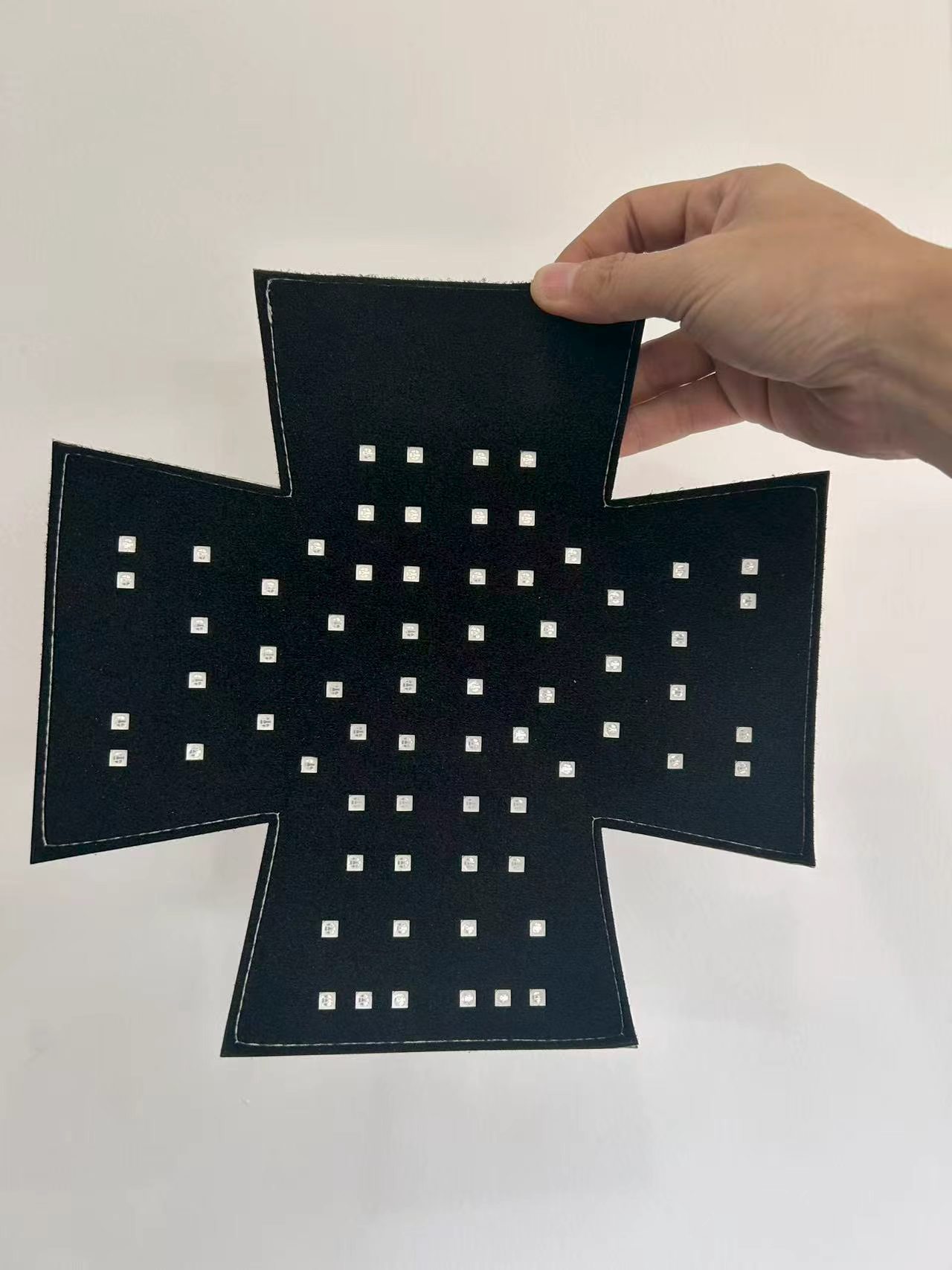
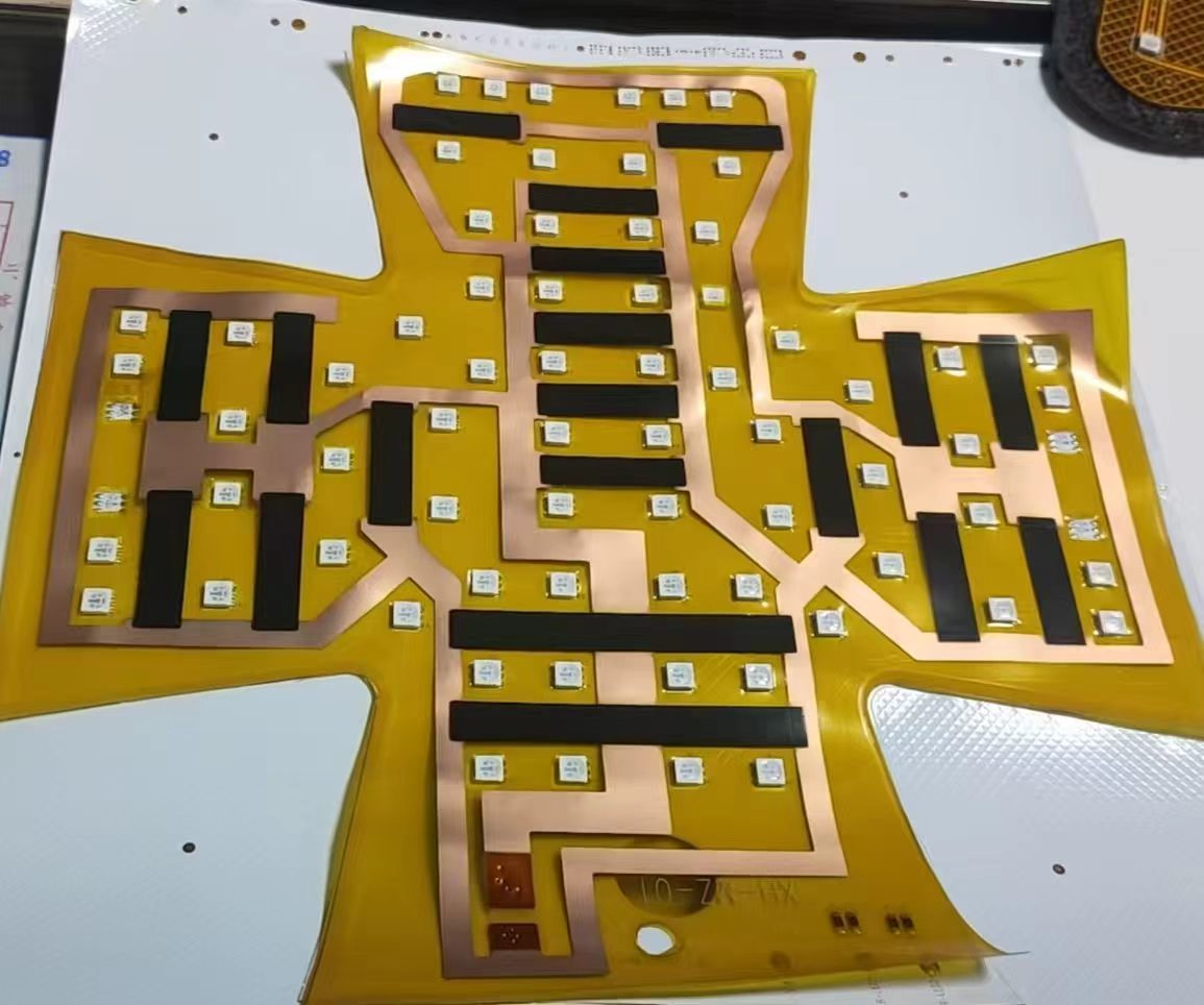
A custom-contoured wearable insert co-developed by XIHE and Lescolton: a flexible circuit carrying graphene far-infrared heating traces and 72 red-blue LED beads on one cross-shaped pad. Power, light and heat in a single thin layer — engineered once, fitted into many cap forms.
01 / Product problem
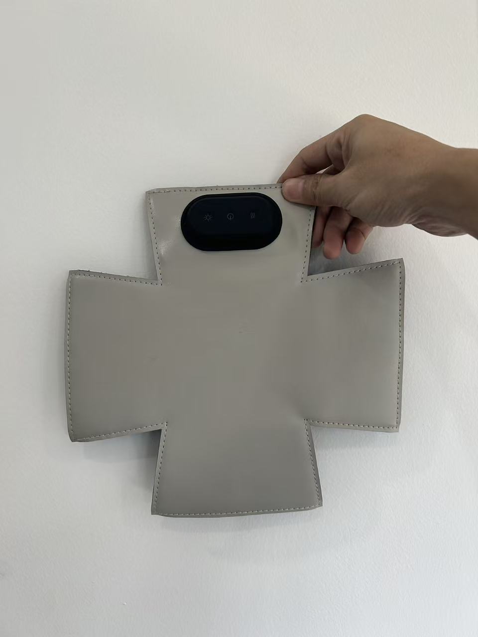
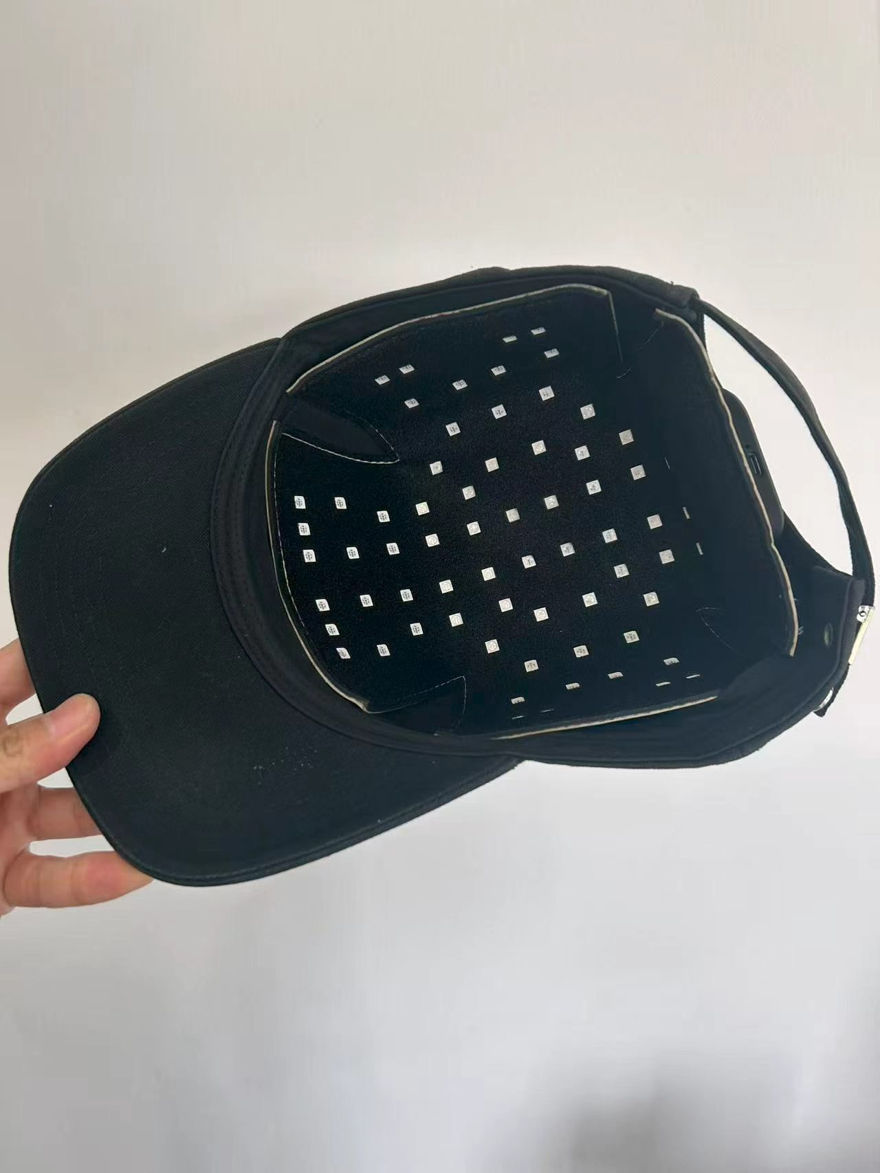
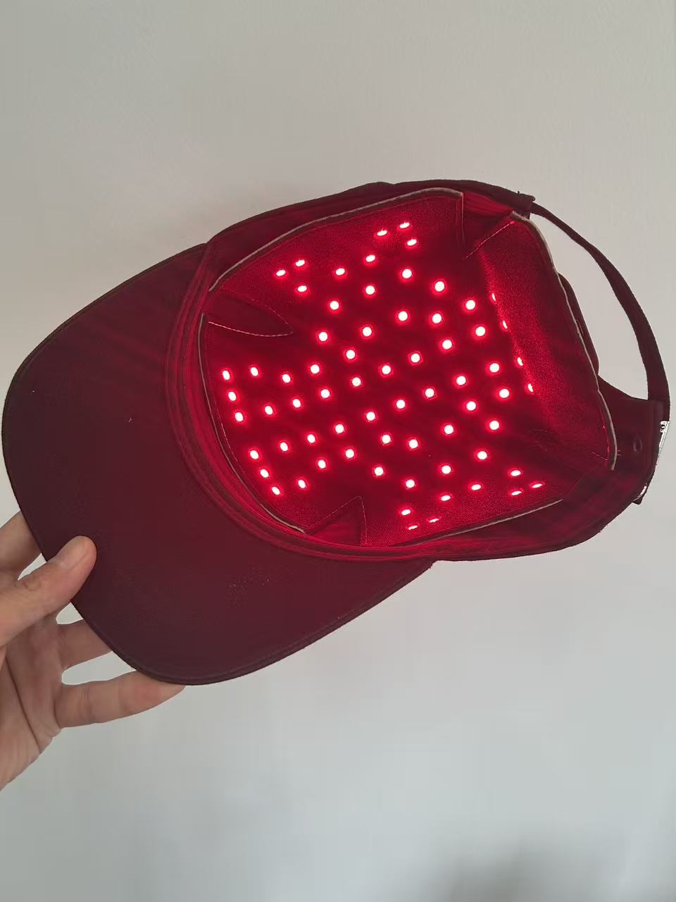
XIHE co-developed this wearable pad with Lescolton. The insert combines a graphene far-infrared heating film layer (5–15 μm band, material level) with 72 LED beads — 650±10 nm red and 470±10 nm blue, dual-color, three light modes (steady / breathing / flashing / off) — on a single flexible circuit cut to a cross-shaped contour. Power-on defaults to steady red light and the power-key indicator stays lit for 3s on boot; a long-press of the light key switches to blue. Heating is a short-press toggle that auto-stops after 15 minutes. A 1500 mAh battery with TYPE-C charging powers the pad; the pad cannot be used while charging — the indicator shows red while charging and goes off when full. The detachable insert fits multiple cap types, and LED count and spectrum can be customized per project.
Integration requirements
Case record
Application & engineering tags
Project status
Development stage is not established by this assessment. Ask for the project-specific record during technical review.
Engineering assessment. Product imagery and proposed architecture do not establish tested performance or commercial development stage.
72
LED beads — 650±10 nm red + 470±10 nm blue, dual-color
3 modes
Light modes — steady / breathing / flashing / off; long-press light key for blue
5–15 μm
Graphene far-infrared band — material-level figure
1500 mAh
Battery capacity; TYPE-C charging; not usable while charging
02 / Integration structure
The flexible circuit carries both the graphene heating traces and the 72-bead LED array. Power, light and heat share one thin layer instead of three stacked assemblies — a thinner insert, fewer interconnects, one integration point for the cap maker.
The cross-shaped contour was cut for the cap interior; the circuit pattern, bead placement and heating traces were then drawn to that contour. The form defines the circuit, not the other way round — which is why the same engineering approach ports to other wearable forms.
This is what XIHE means by Custom Heating Integration: one engineered heating-and-light layer, fitted into many end-product forms. The LED count and spectrum are customizable per project — the integration pattern is the product, not just the pad.
Assembly detail
The pad as built: the heating-and-light layer, the control and power, and the detachable form that fits many caps.
Co-developed by XIHE and Lescolton. Flexible pad insert with 72 red-blue LED beads (650±10 nm / 470±10 nm), graphene far-infrared layer (5–15 μm, material level), 1500 mAh battery with TYPE-C charging.
Thermal interpretation
Spatial uniformity describes variation across an area. Control stability describes variation over time at one location.
The graphene film provides the far-infrared heating layer (5–15 μm, material-level figure); the LED array provides 650 nm red and 470 nm blue output. Both are driven from the same flexible circuit.
72 beads, 650±10/470±10 nm wavelengths, 3 light modes, 15-minute heating auto-stop, 1500 mAh and TYPE-C are product-configuration figures. The 5–15 μm band is a material-level figure for the graphene heating film.
No efficacy, wellness or hair-regrowth claims. This record describes the engineered insert only — not outcomes, not medical effects.
03 / Engineering validation
Proposed verification work. Test conditions and acceptance limits must be set for the specific assembly before testing begins.
| Integration challenge | Possible physical mechanism | Proposed verification method | Engineering decision to evaluate |
|---|---|---|---|
| LED bead dropout on flexing | Repeated bending stresses solder joints on the flexible circuit. | Flex-cycle the insert and re-test every bead; check graphene trace continuity at the same time. | Circuit layout and bead placement. |
| Hot edge where traces converge | Current density rises where heating traces narrow near the contour edge. | Thermal-map the pad surface under full heat mode; verify spread against the acceptance rule. | Heating-trace geometry. |
| Configuration figure quoted as material figure | The 5–15 μm band gets repeated as a product-level claim. | Label the band as material-level in every figure table; keep product configuration figures separate. | Evidence scope and permitted wording. |
Engineering record for the co-developed insert. Figures describe the pad configuration and the graphene film at material level; they do not establish wellness, efficacy or medical outcomes. Co-developed by XIHE and Lescolton.
04 / Development stage
Confirm the project-specific stage and evidence before treating an assessment as a qualified production program.
Engineering handoff records
05 / Next step
Review component scope, check the Engineering evidence, and bring your project requirements to a Technical Review.
Review the component and supply scope.
Define the validation record the decision needs.
Share the geometry, electrical input and development stage.
Related integration formats
Share the product geometry, layer stack and operating conditions. We will review the heating architecture and the questions a sample needs to answer.
Start Technical Review