QUICK TAKE
Carbon fiber is a mature, low-cost baseline for static, budget-constrained heaters. PI graphene heating film wins when the product brief requires continuous flexing, hotspot-free surface uniformity, or verified far-infrared output. This page compares both across conductive architecture, flex fatigue, thermal uniformity, FIR characteristics and resistance stability — with test conditions on every number.
Executive Summary (Engineering Quick Verdict)
Choose carbon fiber heating elements if: your application involves static, non-flexing panels, has a strictly constrained BOM budget, can tolerate minor linear temperature gradients, and relies primarily on conductive heat transfer.
Choose PI graphene heating film if: your OEM device undergoes continuous mechanical deformation (wearable braces, foldable recovery pads, capsule liners), requires uniform surface heating without wire-track hotspots, or targets verified far-infrared radiant output as a product claim.
Hardware R&D engineers and ODM sourcing managers developing recovery capsules, heated wearable orthotics, and flexible thermotherapy pads frequently encounter the same reliability bottleneck during lifecycle testing: filament breakage under repeated flexing, localized thermal hotspots, uneven heat distribution, and progressive wattage decay.
While carbon fiber heating wire is a mature, widely adopted baseline in the industry, polyimide (PI) graphene heating film represents a fundamentally different planar heating architecture. Rather than relying on discrete linear filaments, it operates as a continuous conductive plane.
Below is an objective, measurement-driven comparison of both technologies across electrothermal physics, mechanical fatigue resistance, and radiant heat transfer to support your OEM component selection.
1. Fundamental Electrothermal Architecture: Linear Filaments vs. Planar Conduction
Carbon Fiber Heating Elements (1D Linear Conduction)
Carbon fiber heaters generate heat through twisted bundles of discrete carbon filaments arranged in a serpentine or parallel wiring pattern. Because current flows along individual fiber tracks held in place by a carrier substrate, mechanical stress from bending, folding, or tension concentrates heavily at filament nodes and turn radii.
When a single fiber bundle fractures due to cyclic fatigue, the local cross-sectional area of the circuit changes abruptly. This triggers a spike in local electrical resistance — leading either to localized thermal runaway (hotspots) at the fracture site or complete open-circuit failure.
PI Graphene Heating Film (2D Planar Conduction)
A PI graphene heating film is engineered by precision-coating a homogenized graphene conductive slurry onto a high-temperature polyimide (PI) substrate, forming a continuous, interconnected two-dimensional conductive lattice.
Because electrical current and thermal generation occur synchronously across the entire surface plane, there are no discrete filament nodes. Mechanical bending stress is distributed evenly across the flexible polymer-graphene matrix, eliminating the single-point filament fracture vulnerability inherent to wire-based heaters.
2. Engineering Parameter Comparison: Carbon Fiber vs. PI Graphene Film
| Engineering Metric | Carbon Fiber Heating Element | PI Graphene Flexible Heating Film | Test Standard / Method |
|---|---|---|---|
| Conductive Architecture | Discrete 1D twisted fiber bundles (linear) | Continuous 2D coated conductive lattice (planar) | Structural classification (industry standard terminology) |
| Typical Thickness | 0.8–2.5 mm (excluding outer jacket; industry typical) | Project-specified — defined by substrate, functional layer and encapsulation for the specific product | Micrometer measurement (cross-section) |
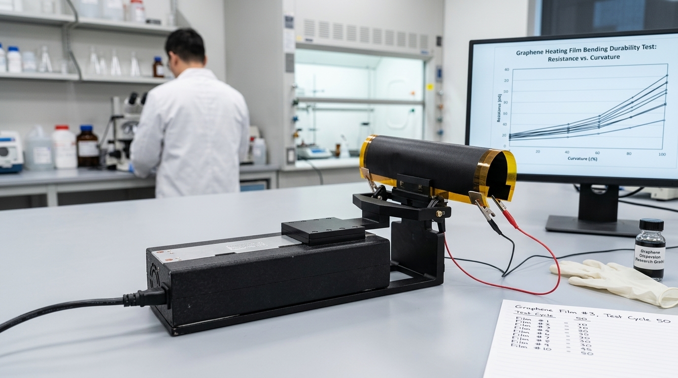
| Flex Fatigue & Bending Life | ~1,000–5,000 cycles at 20 mm bend radius before noticeable resistance drift (industry typical). Stress concentrates at fold lines; filaments micro-fracture under high-cycle flexing, causing resistance spikes or open circuits. | 10,000 cycles at 10 mm bend radius, 100 mm/s, resistance shift ΔR/R₀ = −0.9% measured after 1 h rest (XIHE lab record, industry-standard drafting comparison sample 1-1). Stress distributes across the plane instead of concentrating at filament nodes. | Cyclic bending under the defined test conditions; resistance measured via 4-wire method pre- and post-cycling |
| Surface Thermal Uniformity | ±3–5°C typical across the heating surface (industry typical; depends on wire density and pitch). Heat concentrates along wire tracks with cooler zones between gaps; insufficient routing density creates noticeable thermal striping and hotspot risks. | ±1.5°C on precision heater modules and ≤2.4°C across large-format panels (XIHE lab records, IR thermography). Planar conduction eliminates wire-track hotspots at the physics level; XIHE’s published system-level record adds a 220-point receiving-plane grid on a suspended livestock panel (V2 iteration: 6.0°C spatial spread). | IR thermography (FLIR) at steady-state rated power; grid-based receiving-plane measurement |
| Far-Infrared (FIR) Characteristics | Normal emissivity ~0.70–0.85 (industry typical range for oxidized carbon fiber surfaces). Energy transfer is dominated by contact conduction rather than radiant output. | Normal total emissivity 0.88 — measured on XIHE delivered sample FIHF-7.9V-6.7W only (NIQS report (2022) WT-HW-00529, 2022-07-29, GB/T 7287-2008 Ch.18 Method B). This is a sample-scoped material property, not a blanket specification for every XIHE film or finished product. | NIQS test report for the identified sample; do not extrapolate to other configurations |
| Long-Term Resistance Stability | Irreversible resistance surge once individual fiber strands begin to fray or snap under thermal-mechanical cycling. | Highly stable resistance profile across repeated thermal cycling and dynamic flexing, provided encapsulation remains intact (see failure modes below). | Resistance monitoring over accelerated thermal-mechanical cycling; ΔR/R₀ tracking |
| BOM Cost & Manufacturing | Low raw material cost; simple routing process; widely available in commodity-grade supplies. | Higher material and precision coating yield costs; requires strict slurry dispersion and micron-level thickness control. | Industry cost-structure analysis (commodity wire vs. precision coating) |
3. Real-World OEM Failure Modes & Reliability Boundaries
In dynamic applications — such as recovery beds, heated lumbar support belts, chamber liners, and wearable wraps — the heating element must endure constant compression, torsion, and folding alongside human movement.
Why carbon fiber fails in the field: the majority of post-market warranty claims (RMAs) for carbon fiber pads originate at habitual crease zones. As individual micro-filaments brittle-fracture over months of use, users first experience uncomfortable pinpoint heating (localized hotspots), followed shortly by complete device failure when the circuit severs.
Why planar graphene survives dynamic loads: without independent wire strands to snap, a properly laminated PI graphene film absorbs flexing without severing the conductive pathway, directly reducing field failure rates in deformable hardware.
What can cause planar graphene film to fail:
While graphene’s 2D architecture eliminates filament breakage, it is not indestructible. The primary failure modes in PI graphene heaters are:
- Electrode delamination at the bus-bar interface if adhesion is poorly controlled, especially under high-humidity cycling.
- Silver migration from silver-based electrode traces under prolonged DC bias in high-moisture environments, which can create localized conductivity paths.
- Edge cracking or pinhole propagation if the film is subjected to crease radii below the specified minimum or sharp mechanical punctures.
- Encapsulation breach that allows moisture or contaminants to reach the conductive layer, accelerating resistance drift over time.
This is why proper encapsulation design, electrode material selection, and application-specific bend-radius derating are critical engineering inputs during the OEM review — not afterthoughts.
Critical Engineering Caveat (The Slurry & Coating Boundary)
Not every product marketed as a “graphene heating film” delivers planar uniformity. Low-cost imitations on the market frequently use poorly dispersed carbon-black blends or rudimentary screen-printing with inconsistent wet-film thickness. Poor slurry dispersion and uneven coating thickness will produce severe hotspots and rapid resistance decay — performing worse than standard carbon fiber.
True planar reliability depends on three verified manufacturing controls: raw graphene purity, micron-level slot-die/micro-gravure coating uniformity, and laminated encapsulation integrity. Material labels alone do not guarantee finished device performance.
4. OEM Decision Matrix: Which Technology Fits Your Hardware?
When to Specify Carbon Fiber Heating Elements
- Static or Rigid Installations: Flat warming boards, fixed architectural panels, or rigid enclosures where the heater will never be folded or compressed after assembly.
- Typical use cases: Industrial cabinet heaters, built-in seat warmers, rigid backrest panels.
- Cost-Driven Commodity Products: Entry-level consumer warming goods with tight BOM ceilings where thick insulation layers can mask wire-track temperature gaps.
- Typical use cases: Budget heating pads, basic pet warmers, low-cost foot warmers.
- Purely Conductive Heating Needs: Applications that only require basic temperature elevation without specific far-infrared spectral requirements.
- Typical use cases: Enclosure anti-condensation heaters, pipe trace heating.
- Mature Supply Chain & Low Tooling Entry: Established manufacturing base with low NRE cost for simple wire layouts; fast quoting for standard shapes.
- Typical use cases: High-volume consumer products with simple rectangular or serpentine patterns.
When to Specify PI Graphene Heating Film
- Dynamic & Deformable Hardware: Wearable heated braces, foldable thermotherapy mats, and capsule liners subject to continuous bending, rolling, or mechanical vibration.
- Typical use cases: Heated knee/back orthotics, foldable recovery pad liners, cabin and capsule heating inserts.
- Strict Surface Temperature Uniformity: Wellness and personal-care devices in close skin proximity where localized hotspots must be eliminated at the physics level.
- Typical use cases: Wearable warming pads, foldable recovery mats, cabin liners.
- Ultra-Thin & Lightweight Integration: Compact industrial or wearable designs requiring sub-millimeter heater profiles and rapid thermal response. Final thickness is project-specified — substrate, functional layer and encapsulation are defined per product.
- Typical use cases: Smart garment heating elements, foldable device thermal management, thin-form sensor housings.
- Verified Far-Infrared (FIR) Output: Wellness and agricultural warming systems engineered around radiant energy transfer — where the FIR claim is backed by a named test report on an identified sample, not a generic material label.
- Typical use cases: FIR warming mats, livestock farrowing-zone heaters, radiant cabin panels.
5. Frequently Asked Questions (FAQ for OEM Engineers)
Does PI graphene heating film require a different temperature control strategy than carbon fiber?
Both technologies require NTC thermistors or RTD sensors paired with PWM/PID controllers for closed-loop safety. However, because PI graphene film has extremely low thermal mass and responds within seconds, your thermistor placement reaches thermal equilibrium much faster — preventing the temperature overshoot commonly seen when sensing between spaced carbon fiber wires.
How should an OEM verify the quality of a graphene heating film sample before tooling?
Do not rely solely on single-point multimeter resistance checks. Engineers should perform: IR thermography (FLIR) mapping under rated voltage in open air to inspect for coating streaks or edge hotspots; cyclic bending fatigue tests (e.g., 10,000+ cycles at target bend radius) measuring pre- and post-test resistance drift (ΔR/R₀); and third-party emissivity verification (such as a NIQS test report) if far-infrared performance is part of your product claim.
Can PI graphene heating films be powered with standard PWM/PID temperature controllers?
Yes. PI graphene heating films behave as resistive loads and are compatible with standard PWM and PID control architectures. Due to their low thermal mass and fast thermal response, graphene heaters can track set-point changes more tightly than wire-wound elements with comparable sensor placement. For battery-powered DC designs, we recommend specifying NTC thermistor placement during the prototyping phase to optimize closed-loop response time and prevent overshoot.
Start Your Technical Evaluation
Evaluating a transition from wire-based heaters to planar graphene film? Provide your target geometry, operating voltage (5–240 V, AC or DC), target surface temperature, and bending radius requirements.
Start a Technical Review with XIHE Engineering | Explore the Graphene Heating Film Platform