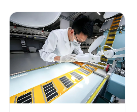
Solution · By Engineering Requirement
Large-Area Heating
Coordinate electrode geometry, power distribution and edge conditions across a larger surface.
Buyer question
Can the architecture distribute heat across the required surface and its edges?
Heating component
Graphene Heating Film
Review the component construction, available supply formats and integration requirements.
Validation evidence
Engineering Evidence
Translate the requirement into a sample, method, conditions and acceptance decision.
01 · The challenge
The engineering requirement.
Deliver the specified heat distribution over a defined assembled area.
- Electrical geometry does not scale independently of voltage and power density.
- Busbar and connection losses can create local heating outside the active area.
- Edges, panel gaps and supports introduce different thermal boundaries.
02 · Design approach
The graphene heating film architecture.
The film is designed as part of the product build — layer by layer, with the electrical and mechanical constraints stated up front.
- Evaluate sheet resistance, electrode spacing and current-carrying width together.
- Compare a continuous panel with independently controlled sections.
- Define the measurement region before agreeing to a uniformity target.
What this enables for your product
Extend heating across the usable surface instead of concentrating it in a small region. Electrode layout, panel boundaries and zones give the team practical ways to address edge losses and uneven power distribution.
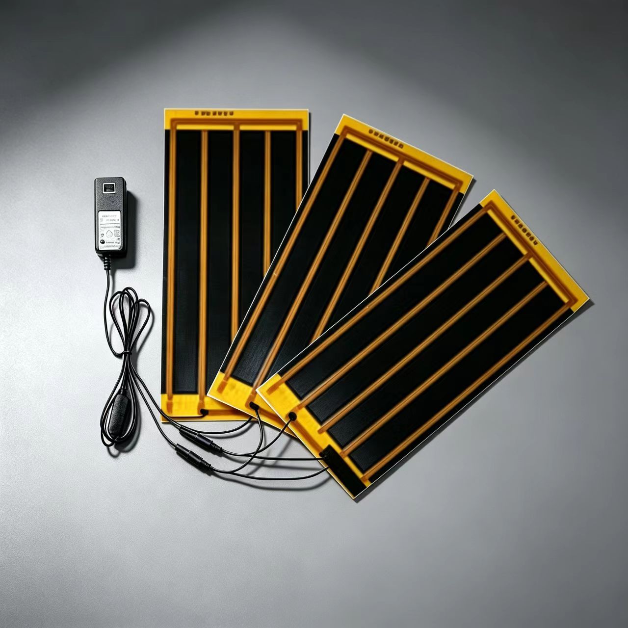
- 01
Substrate / panel
- 02
Printed functional layer
- 03
Electrode layout
- 04
Lamination
- 05
Controller interface
03 · Engineering parameters
The parameters that decide this design.
Agree these inputs before selecting a film configuration or requesting a sample.
| Design input | What to establish |
|---|---|
| Active area | Dimensions, gaps, electrode placement and excluded regions. |
| Electrical distribution | Zone current, busbar loss and connection resistance. |
| Thermal boundary | Frame, support, facing material and exposed edges. |
| Uniformity | Measurement grid, averaging rule, maximum spread and settling condition. |
Validation focus
Map the full assembly and log branch currents. Include edge and seam measurements instead of reporting only a centre region.
04 · Relevant case studies
Explore the assembly decisions.
Explore existing product integrations and engineering assessments. Each record identifies the product context, design decisions and validation scope.
Existing product integration
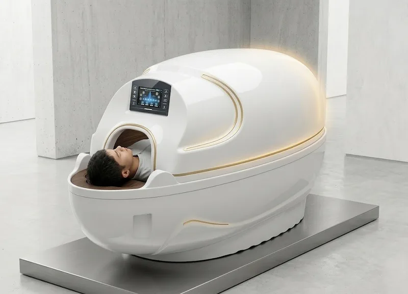
Capsule Heating System
Existing XIHE Capsule products combine upper-cabin and lower-mattress graphene heating. Explore the system architecture and discuss OEM adaptations for your product.
XIHE Capsule product archive visual.
View →Engineering assessment
Large-Area Heating System
Scaling a heating surface changes electrical distribution, thermal boundaries and assembly tolerances. The area must be engineered as a system.
View →05 · Prototype to production
The route from requirement to production.
Agree the required deliverables before moving from a sample to a pilot build.
- 01
Requirement Review
- 02
Heating Architecture
- 03
Prototype Development
- 04
Engineering Validation
- 05
Pilot Production
- 06
Mass Production
Define sample identity, test conditions and acceptance criteria with the Engineering evidence centre before releasing a configuration for the next build stage.
Does this match your requirement?
Describe the product, the heating area and the electrical constraints. We will review the heating architecture with you.
Start Technical Review