Case Studies / Engineering assessment
Large-Area Heating System
Scaling a heating surface changes electrical distribution, thermal boundaries and assembly tolerances. The area must be engineered as a system.
01 / Product problem
A panel-based architecture for a larger heated surface.
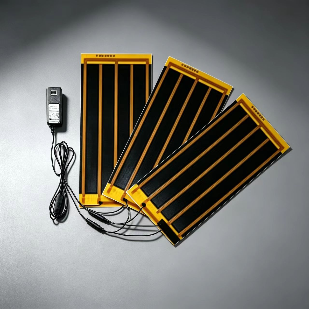
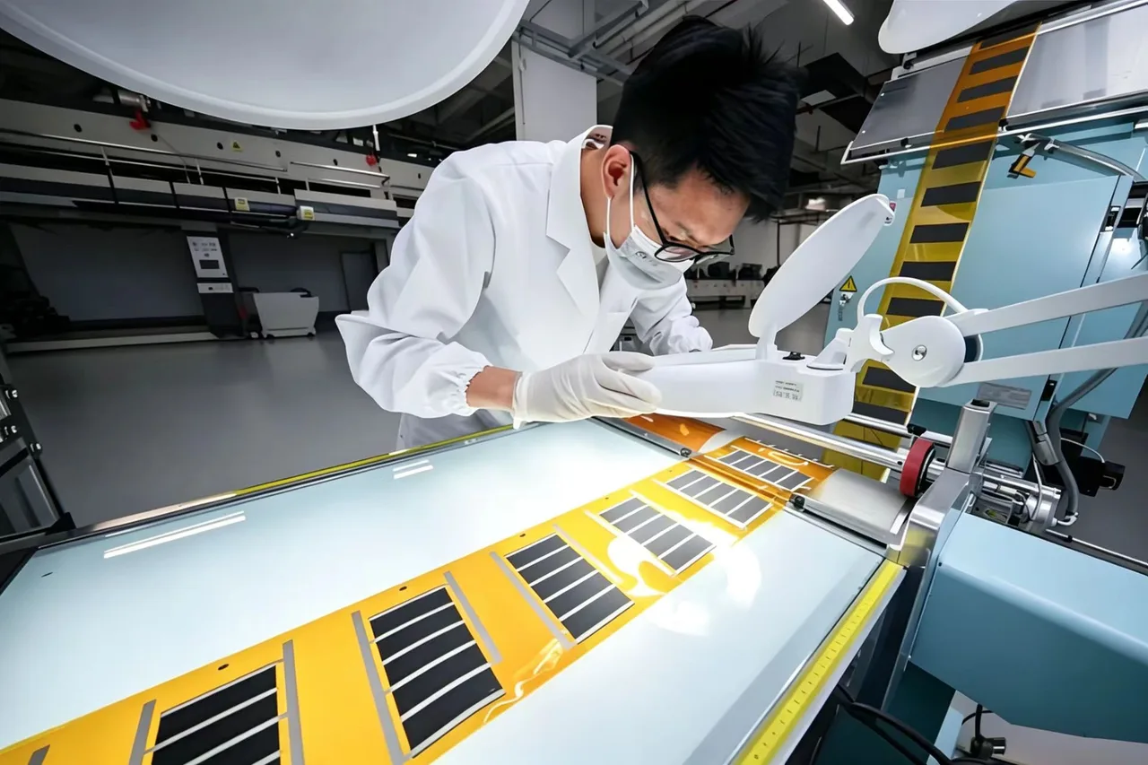
The film supply and enclosure records support discussion of panel-based heating architectures. An identified customer installation and a project-specific validation record are not supplied; this page is an engineering assessment rather than a completed deployment claim.
Integration requirements
- Specify active area, panel boundaries and acceptable temperature variation.
- Match total current and branch distribution to the available supply.
- Define substrate, insulation and exposed-edge conditions.
- Account for connections, expansion and replacement access.
Case record
Application & engineering tags
Project status
Development stage is not established by this assessment. Ask for the project-specific record during technical review.
Engineering assessment. Product imagery and proposed architecture do not establish tested performance or commercial development stage.
02 / Integration structure
Design the interfaces around the heater.
Scaling electrical geometry
For an ideal uniform sheet with full-width busbars, resistance depends on sheet resistance and the ratio of electrode separation to current-carrying width. Simply enlarging both dimensions does not preserve power density at the same voltage. Review geometry, busbar loss and available current together.
Panel boundaries and thermal edges
Panel gaps, frame contacts and exposed edges create different heat-loss paths. A global average can hide a cold seam or a local hotspot. Specify both the measurement region and how panel boundaries are included in the acceptance rule.
Zoning and tolerance
Parallel zones can shorten current paths and allow separate regulation, while increasing harness complexity. Evaluate variation in resistance, bonding and thermal contact across assemblies. A successful single coupon is not evidence of full-area consistency.
Assembly detail
Trace the electrical and thermal paths.
A representative design assessment. Final materials, geometry and sensing positions belong in the project drawing.
Existing heating-component visual. It illustrates the component format, not a verified installation or production scale.
03 / Engineering validation
What could fail, and how to investigate it.
Proposed verification work. Test conditions and acceptance limits must be set for the specific assembly before testing begins.
| Integration challenge | Possible physical mechanism | Proposed verification method | Engineering decision to evaluate |
|---|---|---|---|
| Cold seams or hot electrode ends | Unequal heat loss or current concentration near boundaries. | Map the full assembly, including edges and inter-panel joints, at defined input and ambient conditions. | Panel layout, busbars and measurement region. |
| Connection heating | Branch current and contact resistance create local dissipation. | Measure branch currents, voltage drops and connection temperatures together. | Interconnect design and inspection. |
| Variation between builds | Electrical and lamination tolerances combine at system scale. | Compare multiple identified assemblies using the same operating and measurement setup. | Process tolerance and production acceptance plan. |
This assessment does not establish an installed customer system, capacity figure or measured full-area uniformity. Those require an identified project and test record.
04 / Development stage
Development stage is not established by this assessment.
Confirm the project-specific stage and evidence before treating an assessment as a qualified production program.
Engineering handoff records
- Full-area panel and zone layout.
- Power-distribution and connector schedule.
- Grid definition covering panel centres, edges and seams.
- Build-to-build electrical and thermal comparison.
05 / Next step
Move from this record to your product decision.
Review component scope, check the Engineering evidence, and bring your project requirements to a Technical Review.
Graphene Heating Film
Review the component and supply scope.
Engineering Evidence
Define the validation record the decision needs.
Technical Review
Share the geometry, electrical input and development stage.
Related integration formats
Explore another assembly.
Working on a similar assembly?
Share the product geometry, layer stack and operating conditions. We will review the heating architecture and the questions a sample needs to answer.
Start Technical Review