Start Technical Review
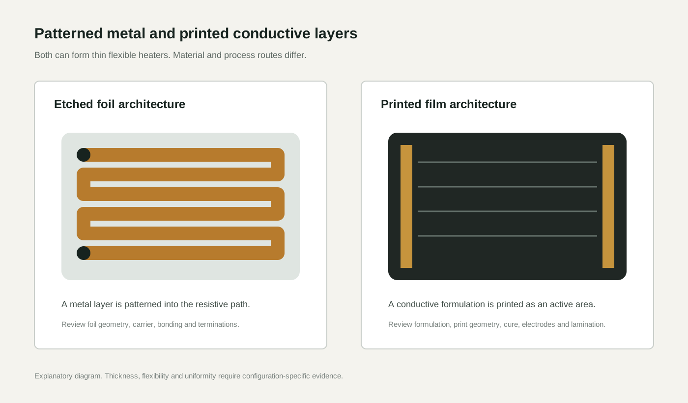
Explanatory comparison of a patterned etched-metal path and a printed conductive heating area

Graphene Insights · Engineering notes

Graphene Heating Film vs Etched Foil Heater

Etched foil heaters and graphene heating film both serve flexible-heater design, but they solve different engineering problems. Compare them by architecture, not by temperature.

heating-film-design 5 min read Updated 2026-08-01

Etched foil heaters and graphene heating film are two ways to build a flexible or structured heater, not two fixed performance tiers. Etched foil uses a patterned conductive metal layer; graphene film uses a printed conductive layer. Both can be built thin and flexible — a thin etched foil on a polymer substrate is a standard flexible-heater construction. Thickness, conformity and uniformity are set by the complete stack, layout, mounting and control, not by the material category. Choose by the construction and validated result that fits the product.

Explore the component

Flexible Heating Solutions

Review the component, available supply formats and integration requirements for your product.

Engineering note 1

Why flexible-heater comparisons must be architecture-led

Calling both options heating elements hides the real difference. Etched foil builds heat from a patterned conductive metal layer; graphene film builds heat from a printed conductive layer. Each offers different patterning routes, integration options and supplier evidence requirements. The useful comparison is about what each architecture can be engineered to deliver in a specific product, not about a fixed rank between them.
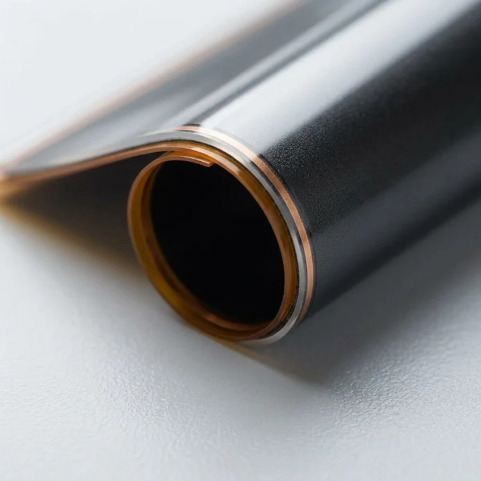
Close view of a thin XIHE heating-film construction curled into a smooth radius
XIHE film-format image. It shows the printed-film side of the comparison; thickness, bend life and thermal behaviour still require configuration-specific records for both heater routes.

Engineering note 2

What the architecture does — and does not — determine

Etched metal foil can be supplied thin and flexible on a polymer carrier; it is not inherently rigid or thick. Equally, a printed film is only as thin and conformable as its substrate, printed layer and lamination allow. Both routes depend on the full construction: carrier material, conductive layer, insulation, adhesive, electrode layout, mounting and control. Judge a candidate by its documented construction and measured result under defined conditions.

Side-by-side

Graphene Heating Film vs Etched Foil Heater

The rows describe the engineering route and the variables that set the result. Neither route is inherently thicker, more rigid or less uniform — thickness, flexibility and uniformity follow from the complete construction and validation on both routes.

Evaluation factorEtched foil heaterGraphene heating film
Design logicHeat follows a patterned conductive metal layer.Heat spreads from a printed conductive layer.
ThicknessSet by metal thickness, carrier and lamination. Thin flexible constructions are standard where the stack allows.Set by substrate, printed layer and lamination. Thin stacks are achievable, subject to the same construction constraints.
FlexibilityA thin foil on a polymer carrier can conform; fatigue depends on foil thickness, geometry and bend radius.A thin printed laminate can conform; fatigue depends on layer position, radius and cycle count.
Heat patternPattern is defined by the etch geometry; the heat map is designable.Pattern is defined by the printed geometry and electrode layout; the heat map is designable.
Best fitProducts suited to metal-foil patterning and its assembly route.Products suited to a printed-area construction and its integration route.
OEM storyMature engineering path with established patterning capability.Material-led differentiation, requiring documented film performance.
Supplier questionWho controls foil geometry, bonding and validated assembly results?Who can document printed-layer construction and integration performance?

Design guidance

When an etched-foil architecture may fit

  • The product suits metal-foil patterning and its assembly route.
  • Precise patterned geometry is a design requirement.
  • The supplier can document foil geometry, bonding and validated results.

Design guidance

When a printed-film architecture may fit

  • The product suits a printed-area construction on the intended substrate.
  • A distributed heating area is part of the requirement.
  • The supplier can document construction, test conditions and integration results.

This comparison is limited to engineering architecture. It does not state that one route is generally thinner, more flexible or more uniform — those properties must be demonstrated for a specific construction under defined test conditions. It does not make any health or therapeutic claim.

Next decision

Return the research to a product decision.

Review the component options, check the engineering evidence, or bring your requirements to a Technical Review.

Flexible Heating Solutions

Review component options and integration requirements.

Engineering Evidence

Translate the comparison into a sample, method, conditions and acceptance rule.

Technical Review

Apply the question to your geometry, electrical input and development stage.

Which question matters to your project?

Share the product, electrical input and assembly conditions to make the discussion specific.

Start Technical Review